Compushift 3
(View Product)
-
FAQs
Can I use the Compushift on my Disco 2 ?
This can be done but note there will be some other issues to address because you wont have the XY switch to give data to the Body Control Module,
reverse lights,
gear position on the dash pod will be lost,
-
Installation
Installation instructions for fitting to the ZF 4HP22/24
In the Box there will be:
1 x Compushift ECU
1 x Wiring loom
1 x TPS loom extension
1 x Temperature sensor
If you also purchase our Potentiometer shifter position switch you will also have:
1 x Potentionmeter switch
1 x Mounting bracker
1 x Lever arm
The Parts in Detail
Compushift ECU
This is to be mounted in the cab in a relatively dry position; we usually put them on the middle seat cover so it’s under the centre console.
Wiring Loom
The large plug fits to the ECU
Next to the large plug are 2 wires, white / orange and white / brown - these are used to switch the reverse and starter inhibit relays when you are using the potentiometer type position switch, more on this below.
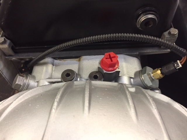
The black round plug fits to the transmission.
The black 2 pin plug is for the ‘Fluid Temp Sensor’.
The plug labelled ‘TPS’ (throttle position sensor) must be wired to give a 0-5V signal to the Compushift ECU. On the TD5 and Tdci you can use the pot on the throttle pedal for this and you will just need to use 2 of the 3 wires, (use TPS extension loom) if the plug is removed from the pot and you look at the pins you will see they are labelled ABCD etc., connect the green wire to the wire that fits to pin F (signal wire), connect the green/white wire to the wire that fits to pin G (earth). On a V8 you can connect these 2 wires to the plenum chamber pot to get this signal, on a Tdi or 2.8 TGV you will have to fit a pot on either the pedal or injector pump. If you are adding a pot for this you will have to also use the green/red wire as the 5V feed.
You now have 2 plugs left, you will only be using one of these and this will depend which type of position switch you are using, if you are using the Disco 2 switch we will have removed a round 5 pin plug and fitted a plug to suit the D2 switch (note there is an additional change for this). If you are using the newer potentiometer type switch you will use the straight 3 pin plug. Fit the relevant lead to the position switch you are using.
You now have 11 loose wires:
Red and black - this is the main feed, to be connected to a clean 12V switched feed, i.e. gets power when the ignition key is turned on. This feed can also be used to power the shifter illumination lights.
White/brown and white/blue - the transmission needs to vary clutch pack oil pressure according to the engine load, there are 2 ways to input this data to the ECU:-
- via the throttle position sensor or
- via the engine MAP sensor. The MAP works much better and these 2 wires are for this purpose, the white/brown goes to
ground and the white/blue goes to the MAP signal wire. More information is on this below.
White/red, White, White/black - These 3 wires can be connected to a momentary rocker switch or paddle switch to allow Tiptronic control, they are upshift, common and downshift.
Blue/orange and Blue/red - The Compushift will let you program many settings in a mode A and a mode B, mode A will be the normal default program, mode B can be programmed with different shift and pressure characteristics which could be a sport mode or tow mode, If the Blue/orange wire is held to ground for 2 seconds using a momentary switch the ECU will switch to mode B parameters, the Blue/red will then get a 12V signal to indicate you are in mode B which can be used to light up a ‘sport’ light etc.
Purple/white - this wire emits a speed signal which can be used for a speedo or cruise control. Not required for the Compushift to function.
Brown - can be used to show engine rpm on display unit but is not required for the Compushift to function.
Temperature Sensor

Position Switch notes
There are 2 types of position switches that can be used with the Compushift, in the past we have used the Disco 2 switch, part number UHB100190 but this has got very expensive so we have looked at alternatives. We have had software written within the Compushift that allows us to use a linear potentiometer linked to the shifter to give a 0-5V signal.
Potentiometer type position switch
Mounting
The potentiometer (pot) can be mounted to the shifter inside the cab or to the gearbox shift lever on the side of the autobox, just check the stroke length before mounting, it’s self -calibrating so just ensure you are not running out of stroke in Park or 1st gear.
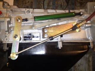
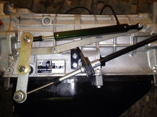
The mounting position will depend on what type of shifter you have in the vehicle, if using our ‘standard’ type shifter, we supply brackets so it will fit like:

Disco 2 type position switch
If you are using the Disco 2 type shifter the mounting will look like:


Potentiometer
The pot must be plugged into the 3 pin plug on the loom,
Compushift loom Pot Function
White Yellow Signal
White/red Red 5v feed
White/black Black Ground
Programming
Search for ‘HGM’ in the ‘App Store’ on your smart phone or ipad, install both ‘CS Setup’ and ‘CS Flash’. Note you will need to be running iOS11 or later.
How to set ‘shift lever voltages’ when using the Potentiometer type switch,
Open ‘CS Setup’, tap ‘pair’, on the Home screen, tap ‘Vehicle Setup’, scroll down to ‘Transmission options’, tap ‘Shift Lever Calibration’.
Put the shifter into Park, tap ‘Set Park’
Put the shifter into Reverse, tap ‘Set Reverse’
Put the shifter into Neutral, tap ‘Set N’
Put the shifter into Drive, tap ‘Set D4’
Put the shifter into 3, tap ‘Set D3’
Put the shifter into 2, tap ‘Set D2’
Put the shifter into 1, tap ‘Set D1’
To check these positions are set correctly, go to the Home screen and tap ‘Diagnostics’, then ‘Transmission Diagnostics’ and check the ‘shift lever position’ agrees with the shifter lever.
Once all wiring is complete the TPS will need to be calibrated. This is done by taping ‘Engine setup’ on the home screen, then ‘TPS Calibration’, when you are ready, tap ‘Start’ and you then have 5 seconds to smoothly press the throttle to full then release to zero. You can check this has worked by tapping ‘Dashboard’ on the home screen and checking the ‘Throttle position’ moves when you press the throttle.
Reverse light switch and Inhibitor switch wiring
When using the Disco 2 type position switch the reverse lights and inhibitor switch wiring comes straight from the switch directly, this is not possible with the Pot type position switch. When the ECU sees the reverse position it gives a 12v feed to the white/orange wire. When the ECU sees the R, D, 3, 2 or 2 position it gives a 12v feed to the white/brown wire. These 2 feeds can be used to drive the relays for the respective switches.
Potentiometer type
Connect the white/orange wire from the Display/programmer to the green/brown wire, the 2 core wire that comes out of this relay needs to be wired through the reverse light circuit.
Connect the white/brown wire from the Display/programmer to the white/yellow wire, the 2 core wire that comes out of this relay needs to be wired through the low current side of the starter motor relay. This will ensure you can only start the engine in Park and Neutral.
Wire the black lead to earth.
Disco 2 type
Starter Inhibitor switch
Wire the labelled 2 core wire through the low current starter solenoid, so it will only start in Park or Neutral,
Reverse Light switch
Wire the labelled 2 core wire to the 2 wires from the reverse light switch from the manual gearbox.
Compushift Pressure Source
The Compushift uses both the throttle position and the MAP signal to set the clutch pack pressures,
TD5 MAP wiring
Connect the white/blue wire to engine ECU top red plug (C0158) pin 6, white/yellow wire
Connect the white/brown wire to ground
Tdci 2.2 MAP wiring
Connect the white/blue wire to engine ECU top plug (C0411) pin 28, blue/green wire
Connect the white/brown wire to ground
Tdci 2.4 MAP wiring
Connect the white/blue wire engine ECU bottom plug pin B1, blue/green wire
Connect the white/brown wire to ground
Miscellaneous Installation notes
We would advise disconnecting the transfer case high/low switch, otherwise the anti-stall gets very confused when in low range, anti- stall is not required with an automatic transmission.
Security Code feature
The new software now has a feature which can be used to write protect all parameters apart from two that are required for installation. These two are the ‘TPS calibration’ and ‘shift lever gear voltages’. This feature stops a customer accidentally resetting parameters unintentionally.
This feature will default to unlocked unless it has been supplied specifically for your application in which case it will be locked, if you wish to alter any of the locked parameters please contact us for the access code.