DIFF PEGGING KIT
(View Product)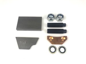
-
Technical
Adjustment procedure :
One screw at a time, using an allen key, hold the screw still, with a ring spanner, back off the locknut, take the screw in until it feels ‘snug’, back out ½ a turn, tighten locknut.
Don’t remove either screw completely.
-
Installation
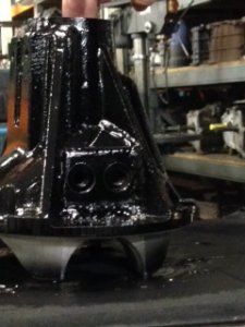
Converting a standard differential casing to an Ashcroft pegged casing.
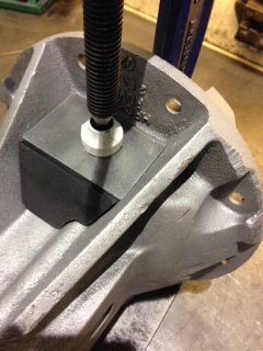
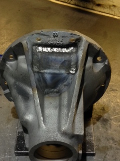
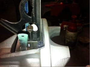
Ensure the casing you are to convert is clean and free of debris, secure the casing in a vice with the pegging area uppermost. Shown below is the area marked out where the pegging plates are to be attached.
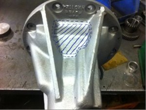
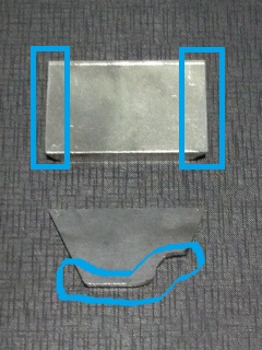
Shown below are the supplied pegging plates (top primary, bottom secondary) that need adjusting to fit your differential casing, the differential casings vary slightly in size and shape due to being a sand casting. The areas shown in the blue boxes on the primary plate are the first areas needing trimming down for a proper fit, this is easiest done with an angle grinder.

It is very important to ensure the primary pegging plate is at a right angle to the differential casing/axle mating face, if the plate is out of square the vital pegging locking nuts will not sit flat and may cause the pegs to release when in use, this will allow the inner phosphor bronze plate to fall into the workings of the differential and potentially damage the components. Some packing strips can be used to ensure the plate sits square prior to welding and be removed once the plate is tacked in the correct orientation.
Trim the secondary supplied pegging plate to fit snug in the exposed area around the front of the primary pegging plate.

We are now ready to start welding, for the welding we use half TIG and half ARC.
Remember when welding, always apply small tacks in the corners of the plates and re-measure, the plates can move through heat transfer and weld contraction so ensure the plates are in the correct position before laying down your main weld.
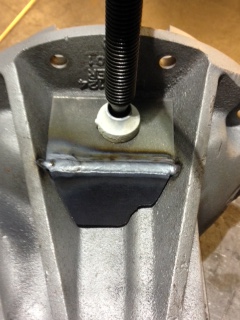
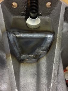
For the TIG we use a normal copper coated steel filler rod and a maximum power of 250 amps. We first weld the primary and secondary plates to each other where they meet.

Next we lay a heavy weld at full power with a slow weave around the secondary plate, fusing it to the casing.
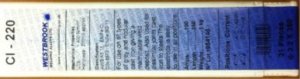
We now change to the ARC welder with a specialist cast iron electrode.
CI-220, 3.2mm diameter x 350
Mechanical properties AMPS..............100
UTS>400N/mm2 LENGTH.........350
Hardness 200HB approx WEIGHT..........1KG
No Lot 1954146
Classification
AWS A5.15:ENiFe-CI Positions Current
DIN8573:ENiFe BG 13 A.C - 40ocv D.C +/-ve
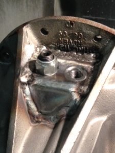
We set the ARC welder to normal steel settings at 85amps, welding with these electrodes feels very odd as the arc is somewhat erratic but the resulting weld is very strong. Lay a weld first down either side of the primary plate.
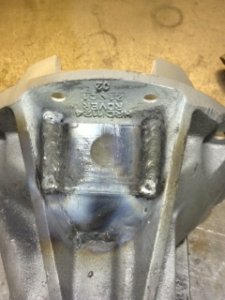
Then weld down the gap at rear of primary plate.

The casing is now ready for machining.
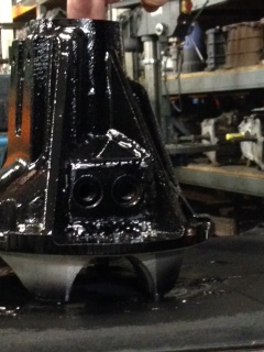
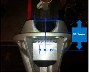
Mount the casing with the differential/axle mounting face and the journal bearing outers absolute vertical on a pillar drill or vertical milling machine table and secure down. Use the diagram below to find your hole centres. Holes should be 36mm apart (18mm each side of centreline) and 94.5mm from centre of end cap.
Using positions shown for following,
(ENSURE HOLES ARE MACHINED IN THIS ORDER)-
-Counter bore to 28.00mm diameter by 1mm deep or till full circle for locking nuts.
-Drill 14.2mm holes (pilot drill first if needed)
-Tap each hole with an M16x2mm tap ensuring cut is square.
The differential casing is now complete, finish with a coat of paint.