Ashcroft Locker - Rover
(View Product)
-
Installation
INSTALLATION GUIDE
We have separated our installation guide into four main categories.
1)Installing your locker into the differential,
Remove the stock diff centre but be sure to mark the bearing caps so they are refitted on the correct side.
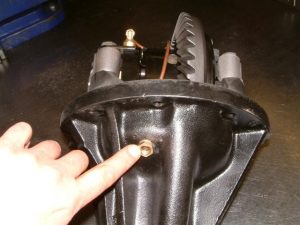
Drill and tap the diff housing, the drill size is 29/64” but 11.5mm will work OK, then tap ¼ BSPF (19 tpi) here:
Fit the crown wheel to the new centre, install locker and set backlash, as per factory spec, to 0.10 – 0.17 mm.
Note you may have to grind the inside of the journal end caps if they foul the centre. There are two lengths of Journal end cap bolts used, 50mm for the non dowelled cap and 60mm for the dowelled cap, select the bolt 5mm longer than stock to fit the cylinder locking tab so that the tab stops the cylinder rotating, see overleaf.
2) Installing the Air Lines
Solenoid connections.
The solenoid is marked as follows and you should connect as shown.
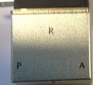 R = Exhaust
P = Air Compressor
A = Diff (blue pipe)
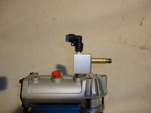
Once the air compressor is mounted remove the nut and coil from the solenoid and fit to the air compressor with the 1/8” BSP M/M nipple, see photo below, it must be this way around:
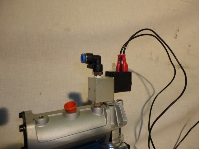
Fit the 1/8” tapered 90 deg push fit elbow to the other port. Refit the coil:

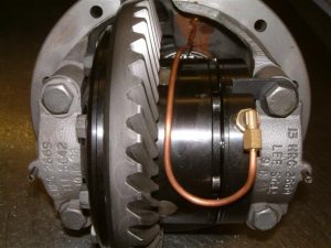
Fit the brass 1/8” parallel 90 deg elbow compression fitting to the locker cylinder and fit the copper pipe to this fitting, pass the other end through the tapped hole in the diff housing. We would suggest fitting the pipe like this to allow some flex in the pipe:
Once the copper pipe is through the tapped hole, fit the brass adapter nut from the outside and mark the pipe flush with the brass nut, remove nut and cut pipe, refit nut, fit one small ‘O’ ring, fit 1/8” parallel 90 deg push fit elbow. Fit air line between this push fit connector and the one on the solenoid.
3) Installing the switches and electrical connections
There are different ways to wire up the switches, assuming you are using the ARB compressor wiring loom they suggest wiring it so the front can only be locked once the rear is already locked, i.e.:
Front switch
Pin 8, ground, on ARB loom use black (either one)
Pin 7, ground, on ARB loom use black (either one)
Pin 2, feed, on ARB loom use yellow
Pin 3, to front solenoid, on ARB loom use dark green
Pin 6, dash illumination, on ARB loom blue/white (shows upper symbol when side lights on)
Rear switch
Pin 8, ground, on ARB loom use black (either one)
Pin 7, ground, on ARB loom use black (either one)
Pin 2, feed, on ARB loom use red
Pin 3, to rear solenoid, on ARB loom use yellow
Pin 6, dash illumination, on ARB loom is blue/white (shows upper symbol when side lights on)
Snip the plug off the yellow and black wires. Crimp on 2 female spade terminals and connect to the parallel pins on the rear solenoid.
Snip the plug off the green and black wire. Crimp on 2 female spade terminals and connect to the parallel pins on the front solenoid.
Final testing
Handbrake off, Centre diff unlocked, mainbox in neutral, Jack up one wheel, the wheel should spin freely,
Switch the air compressor on, allow it to run up to pressure,
Select the locker whilst spinning the wheel and it should stop dead.
Switch the locker off and the wheel should spin freely again.
Torque Settings:
Crown Wheel Bolts 58 Nm
Bearing Caps 90 Nm
PARTS INFORMATION GUIDE
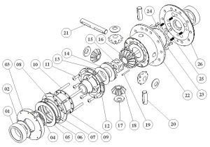
PARTS LISTING
PART NO. DESCRIPTION QTY ASHCROFT PART NO. 1 2 Journal bearings, LR# RTC3095 2 ASH-AL-01 2 Cylinder Thrust Washer 1 ASH-AL-02 3 Cylinder 1 ASH-AL-03 4 Cylinder Bush 1 ASH-AL-04 5 Piston 1 ASH-AL-05 6 Outer O Ring 1 ASH-AL-06 7 Inner O Ring 1 ASH-AL-07 8 Retaining Ring 1 ASH-AL-08 9 Use ASH-AL-24 (M5 x 16 c/skts BZP) 10 ASH-AL-24 10 Selector Cage 1 ASH-AL-10 11 Main Body Screws, M8 x 25 cap low head 8 ASH-AL-11 12 End Cap Small 1 ASH-AL-12 13 Side Gear Washer 2 ASH-AL-13 14 Side Gear, non locking 1 ASH-AL-14 15 Cross Pin boss 1 ASH-AL-15 16 Side Gear, locking 1 ASH-AL-16 17 Planet Gear Washer 4 ASH-AL-17 18 Planet Gear 4 ASH-AL-18 19 Spring Pins, 5/32″ x 1.5″ seloc pins 3 ASH-AL-19 20 Cross Pin short 2 ASH-AL-20 21 Cross Pin long 1 ASH-AL-21 22 Main body 1 ASH-AL-22 23 Lock Ring 1 ASH-AL-23 24 Lock Ring screws, M5 x 16 C/skts BZP 4 ASH-AL-24 25 Return spring 4 ASH-AL-25 26 End Cap Large 1 ASH-AL-26 Note that if you have a turned locker you will need to advise us of this if ordering part number 22 or 26.
In addition to the parts listed above we are also able to supply the following parts:
PART DESCRIPTION QTY ASHCROFT PART NO. 4ml Copper Pipe, 350mm long 1 ASH-AL-27 Actuator Switch 1 ASH-AL-28 Actuator switch fascia – front 1 ASH-AL-29 Actuator switch fascia – rear 1 ASH-AL-30 Air Solenoid Valve 1 ASH-AL-31 90 degrees elbow push fit – ⅛″ bsp taper, (solenoid) 1 ASH-AL-32 90 degrees elbow push fit – ⅛″ bsp parallel (diff housing) 1 ASH-AL-33 Bulkhead fitting adaptor 1 ASH-AL-34 Bulkhead fitting o ring 1 ASH-AL-35 6mm x 5m nylon air line 1 ASH-AL-36 O ring kit (includes Bulkhead, Outer and Inner O Ring) 1 ASH-AL-37 ⅛″ bsp, M/M coupling 1 ASH-AL-38 Journal End Cap M12 x 65 HT Bolt 1 ASH-AL-39 Journal End Cap M12 x 55 HT Bolt 1 ASH-AL-40 Cylinder locking tab 1 ASH-AL-41 ⅛″ bsp, 4mm Comp fitting, 90 elbow 1 ASH-AL-42 ⅛″ bspt 1 ASH-AL-43 Drill bit 29/64” 1 Drill bit Tap ¼ - 19 BSPF Tap Tap All parts listed above are available to purchase at our website, address below
If you have any questions not answered in the information above, please email us as at info@ashcroft-transmissions.co.uk or call us on +44 (0) 1582-496040 and we will be happy to offer further assistance.