TDCi Defender Auto Kit

TDCi Defender Auto Kit

From: £4,415.00

The full price of your kit will be displayed after all options have been selected.

Please note the lead time on this product can be up to 2 months, an estimated date of dispatch will be provided on receipt of your order.

We are able to offer an in house fitting for this kit, please contact Conversions@ashtrans.com for more information.

All prices exclude VAT

Description


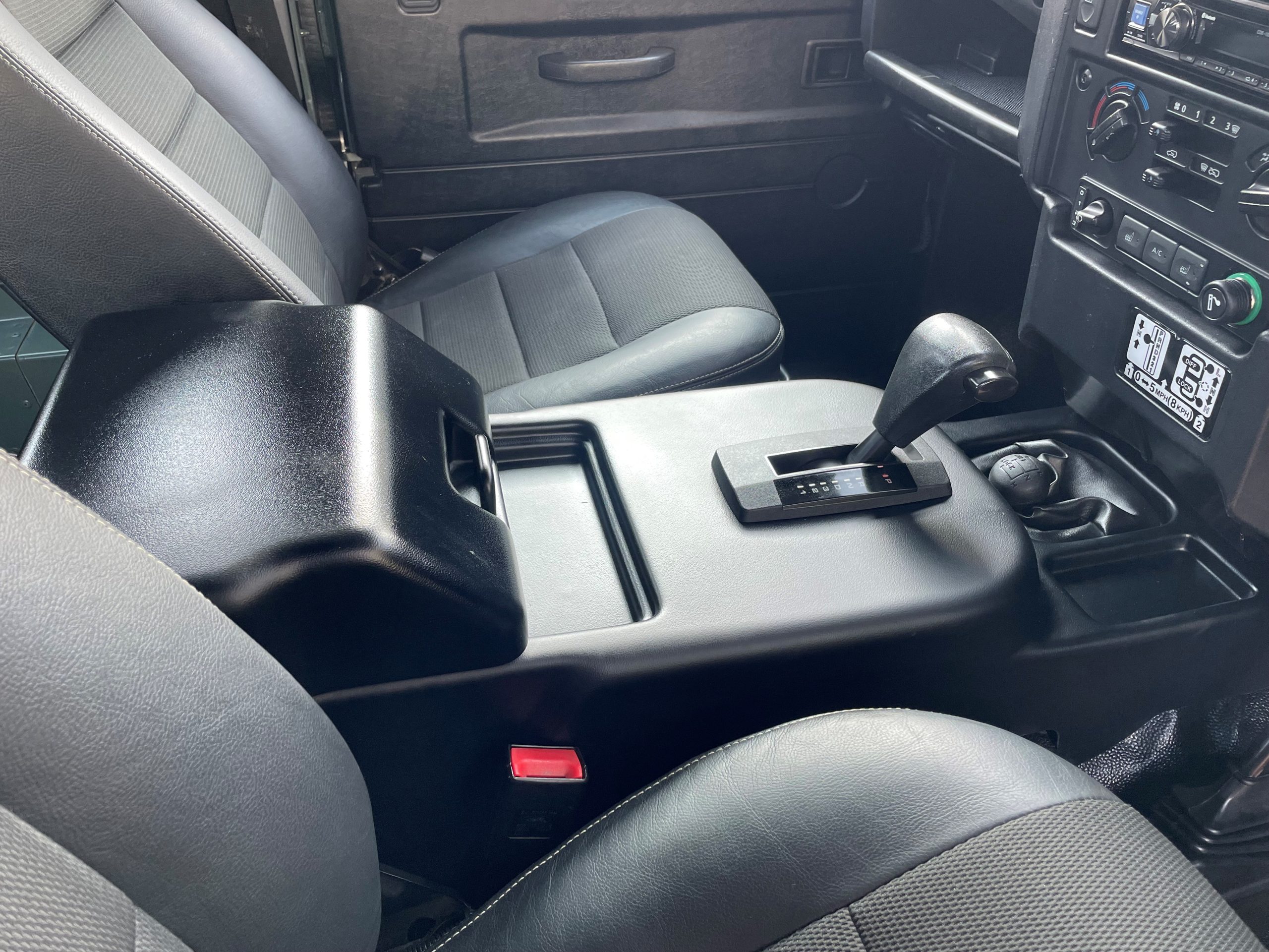
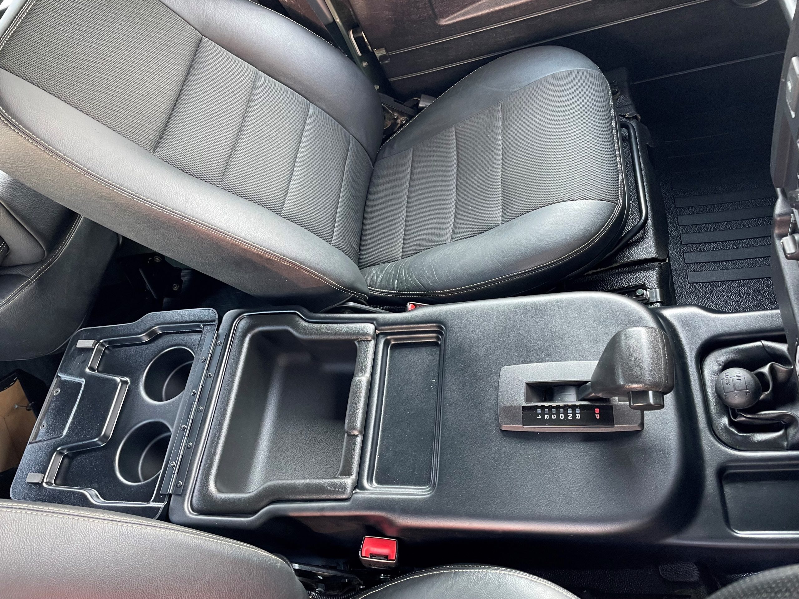
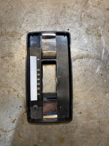
After having successfully marketed the TD5 Defender Auto kit and the natural follow on was the TDCi model when this was introduced in 2007. This was not a simple task and involved considerable development work but we have now successfully being converting the 6 speed manual to a 4 speed auto for some time, on both the 2.4 and 2.2 models.

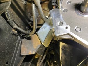
When it was announced the Defender engine was being changed from the TD5 to the 2.4 TDCi we had several enquiries to ask if an auto kit would be available and we started working on it straight away. We bought a Transit 2.4 engine with manual gearbox to allow us to develop a prototype. In the past when we have made up a conversion kit it has been possible to utilise parts from related vehicles in the existing model range, eg some Defender parts, some Disco parts Etc. The 2007 Defender was a much more complex job involving much more design and manufacture than previous kits. Firstly there was no autobox that was a straight fitment to the new 2.4 engine (unlike the TD5) so we needed to make a bellhousing and flexplate assembly from scratch, also the transfer case has been rotated a further 10 deg from the previous position so new mounts were required. There were many small things like this, where with the TD5 kit you would just use a Disco part on the 2.4 it was a case of working out what you need then prototype, test, draw, sample, manufacture Etc.

As always with our conversions we try to keep as near to Factory spec/look as possible this involved keeping the engine and transfer case in “Factory position” so any conversion to automatic box must fit as a direct replacement for the manual box to avoid any propshaft or transfer case changes. The transfer case still functions as normal i.e, with the diff lock and high and low ratios.

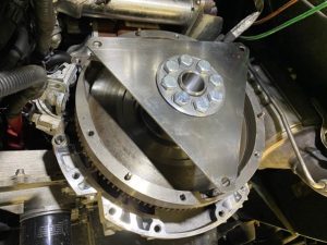
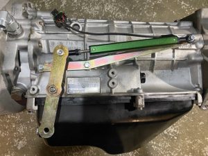
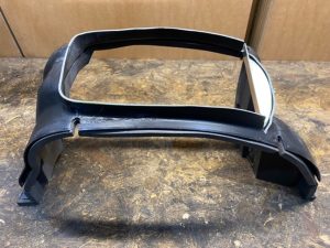
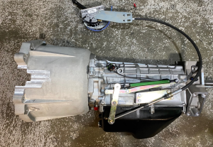
We decided to use the well proven ZF 4HP22EH autobox which was used in the P38 Ranger Rovers and the Series 2 Discovery’s as we have considerable experience with these units and they are readily available. To fit the auto box to the 2.4 engine we manufactured our own bell housing, paying attention to length and orientation of the auto box allowing a “drop in” fit. It was also necessary to design and make a crank boss and flexplate assembly.

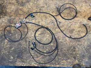
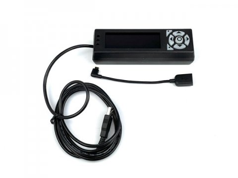
In order to give optimal performance of the auto-box we have developed a “stand alone” control unit called the Compushift . The controller takes signals from the throttle position sensor on the throttle pedal, the speed sensor in the autobox and the gear position switch on the side of the autobox, this information is fed to the ECU and the correct gear selected according to the preset “maps”.

This “electronic” control is a major step forward over the previous “hydraulic” auto-box conversion we had used in the earlier TD5. With this control unit we have a fully adjustable controller allowing us to “customise” or “map” the gear shift to suit each application. It is possible to map the individual shift points and shift pressure v.s throttle position also the torque converter lock up speed and a whole host of other variables.

Great video here of an Australian customer installation :

https://www.youtube.com/watch?v=ze6ow0aVYJk

Please click here to read the article published in the February 2009 issue of Land Rover Monthly and here to read the article in Land Rover Owner in Spring 2008.

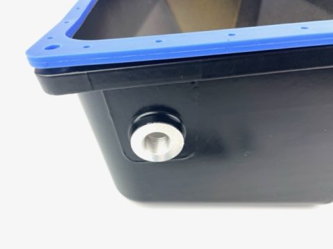
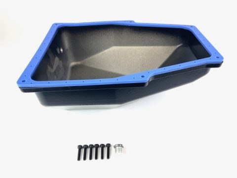
We can also build your unit with our ZF Hi Cap Sump. If you would like this please select in the drop down menu.

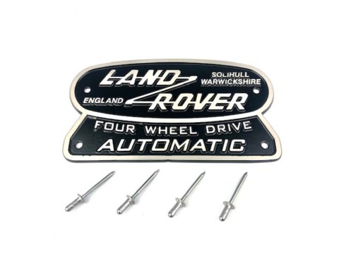
The Defender Auto Plaque is not included the kit but is a nice addition. If you would like this please select from the dropdown menu.

The price shown is for the kit only, However we are able to offer to fit your kit for an additional £1,200 plus vat and this price assumes we keep the manual gearbox. We would require the vehicle is with us for 7-10 working days. Please contact us directly to arrange a fitting appointment.

Shipping Costs

In order to calculate your shipping costs you will need to put the items in your shopping basket and confirm your delivery address. Once you have entered these details a shipping quote will be generated. Please do not proceed to the payment stage unless you are ready to order.

Installation

2007< Defender TDCI 2.4 / 2.2 Auto Conversion Fitting Instructions

Removal of transfer box and MT82 manual gearbox

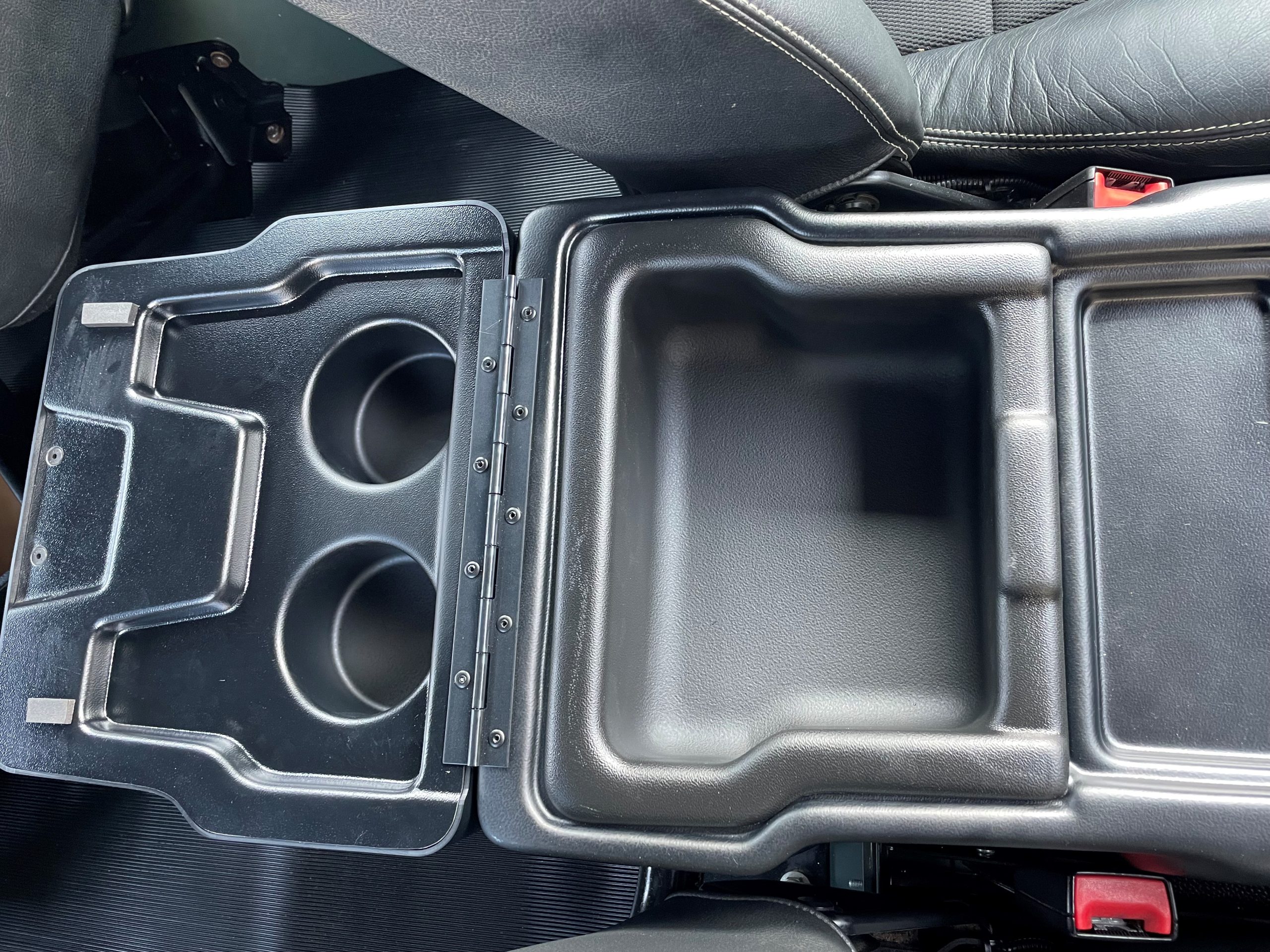
  1. Remove centre cubby box – lift cup holders out to access 2 front fixings, 2 rear fixings inside cubby box.
  2. Remove Centre Cover Plate – pull upwards at the front of plate and slide forwards to remove.
  3. Remove Drivers and Passengers seat bases by pulling up at the front – may need to undo heated seat connector on underside of seat base.
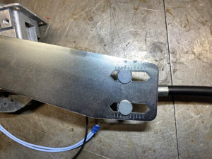
  4. Remove hand brake lever – remove 3 plastic push fittings from gaiter and slide gaiter forwards, undo 2 bolts from lever mechanism to the body, remove pin from cable to lever mechanism and pull mechanism off the cable.
  5. Remove the carpet or rubber mat covering transmission tunnel.
  6. Remove rubber gaiter from gear shifters.
  7. Remove main gearstick by lifting the tabs on each side and pulling upwards.
  8. Remove plastic transmission tunnel – undo 12x screws
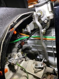
  9. Remove link arm from Hi/Lo lever on transfer box to the Hi / Lo Gear selector – remove black and red connector from link arm.
  10. Undo 8x fixings from gear selectors to the gear selector housing and remove.
  11. Undo 4x fixings holding gear selector housing to gearbox and remove.
  12. Unplug reverse, diff lock and Hi/Lo switches.
  13. Remove transfer case breather hose banjo bolt.
  14. Remove cross member – use a soft mallet if needed.
  15. Drain all oil from transfer box and gearbox (8mm allen for gearbox drain)
  16. Remove both prop shafts – rear prop can be undone at transfer side only and tied to the chassis out of the way.
  17. Split exhaust system at joint in front of centre section, tie centre to chassis so it’s out of the way.
  18. Remove hand brake drum and backplate assembly from transfer box.
  19. Unplug speedo drive connector.
  20. Undo 2x fuel line clips and remove fuel line bracket from chassis.
  21. Remove all ground wires from transfer box.
  22. Remove nut holding transfer mount to chassis
  23. Remove nut holding gearbox mount to chassis
  24. Using the trolley jack raise up gearbox by approximately 20mm
  25. Use transmission jack support transfer box.
  26. Remove 4x transfer box to mount bolts.
  27. Remove all transfer box to gearbox bolts / nuts.
  28. Slide transfer box back from the gearbox, ensure it is clear of the gearbox output shaft and lower down.
  29. Remove 4x gearbox to mount bolts and remove mount.
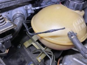
  30. Using transmission jack support rear end of gearbox and remove trolley jack.
  31. Remove clutch line from slave cylinder fitting – drain all brake fluid into oil drain by pumping clutch pedal. Tuck clutch line out of the way, this will be removed after the gearbox.
  32. Remove bracket from DPF to engine.
  33. Ensure crank position sensor wiring is not clipped onto the gearbox and cable tie main loom to the body to keep it out of the way.
  34. Remove all 10x bolt from gearbox bellhousing to engine – you can lower the gearbox down slightly on the transmission jack to help access top 3 bolts.
  35. With a helper separate gearbox from engine and lift over the exhaust pipe and lower down and remove from transmission jack.
  36. Remove clutch line from the body fixing and hard line.
  37. Remove clutch assembly.
  38. Remove flywheel bolts and clean surface.
  39. Remove any studs and dowels from gearbox.Preparing Automatic gearbox and Transfer box for fitting
  40. Install dowels and studs from manual gearbox.
  41. Remove bellhousing cover plate and install the torque converter holding tool and remove the large bracket.
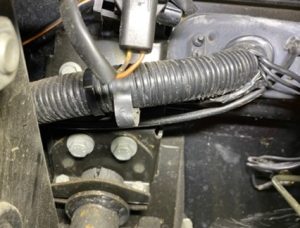
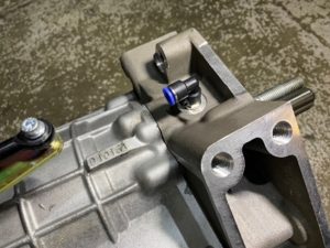
  42. Install breather pipe fitting.
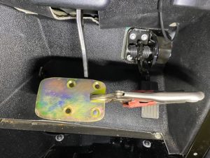
  43. Ensure an oil temperature sensor has been fitted.
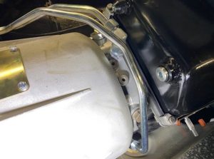
  44. Install oil cooler pipe fittings as shown in picture.


  1. Remove damper and heatshield from original gearbox mount and bolt to the new automatic gearbox mount.
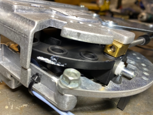
  1. Ensure the transfer box is in Hi ratio and diff lock
  2. Fit a new input seal in transfer box.

Automatic gearbox and transfer box install

  1. Install crank boss on top of the original flywheel with the supplied new bolts and Loctite.
  2. Install flex plate and buttress ring with bolts supplied and Loctite.


  1. With a helper lift the gearbox onto the transmission jack supporting it between the sump and rear housing.
  2. Install gearbox to engine – lift bellhousing over the exhaust pipe whilst the helper pumps up the transmission jack.
  3. Use the supplied cap head bellhousing bolts to install gearbox to engine – the longest bolt supplied should be used in the fixing hole that is also a locating dowel position, it may not be possible to replace the two bolts facing the rear of the vehicle.
  4. Install rear mount to gearbox and locate in chassis support.
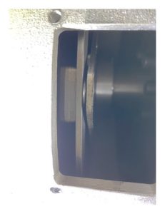
  1. Remove torque converter holding tool and check the gap between the flex plate and torque converter, If the gap is more than 3mm then the gearbox will need to be removed and the supplied spacers fitted behind the flex plate to reduce this gap to 2mm.
  1. Once the gap is correct bolt the torque converter to the flex plate using the bolts provided for this you will need to rotate the engine over clockwise using the bolts on the front crank pulley.


  1. Install bellhousing cover plate.
  2. Install supplied breather pipe into the push fitting and route up the bulkhead along with the vehicle’s other breather pipes, secure breather pipe in engine bay.
  3. Install DPF to engine bracket.
  4. Install Transfer mount into chassis support.
  5. Using trolley jack raise the automatic gearbox roughly 20mm.
  6. Lift transfer box onto transmission jack and raise up to install onto gearbox taking extra care to avoid damaging the input seal – once into position you may need to rotate output flanges to align splines from gearbox to transfer box.
  7. Install bolts from gearbox to transfer box – note the two bolts facing the rear of the vehicle will need to be replaced with bolts that are 30mm long or alternatively cut down original bolts, a full ring of Loctite will also need to be used on these 2 bolts.
  8. Install transfer mount bolts.
  9. Both jacks can now be lowered and removed.
  10. Remove oil fill plug on transfer and fill with new oil (EP80-90) until it spills out of fill hole – use a small amount of Loctite on drain and fill plugs.
  11. Refit transfer box breather pipe.
  12. Reconnect transfer box diff lock switch – The Hi / Lo switch stays disconnected.
  13. Reconnect speedo drive.
  14. Install hand brake assembly.
  15. Refit rear prop shaft.
  16. Refit exhaust system.
  17. Remove top shroud covering viscous cooling fan.
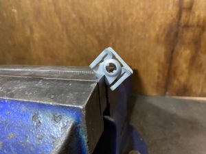
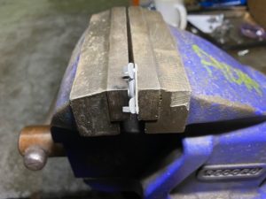
  18. Remove the 2 clips shown in the photo, squeeze together in vice and refit.


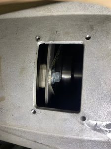
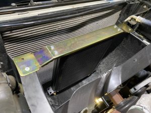
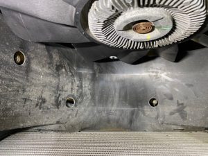
  1. Attach cooler bracket to cooler and place in lower shroud as shown, mark top mounting holes and directly below oil cooler fittings to allow access for cooler pipes.
  2. Drill mounting holes to 6mm and attach using supplied countersunk screws, drill lower holes to 25mm and debur if necessary – use a sheet of metal to hold under lower shroud to protect coolant lines beneath when drilling.


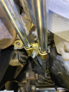
  1. Install oil cooler pipes to gearbox and cooler as shown using provided clamps.


  1. Install front prop shaft.
  2. Install Swan neck and extension bracket with bolts provided.
  3. Attach black and red Hi / Lo connector to new linkage assembly and install on swan neck with supplied bolts.
  4. Ensure full range of motion of both diff lock and Hi / Lo – if diff lock lever is under / over selecting then this can be adjusted with the m8 eyelet bolt. Adjust position of Hi / Lo arm in the red and black connector to adjust its throw.


  1. With the vehicles ignition switched on, check the diff lock light illuminates on the instrument cluster when engaged.
  2. Remove factory dashboard Hi/Lo and Diff Lock instruction sticker, remove glue residue and stick on new supplied instruction sticker.
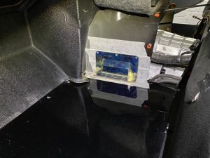
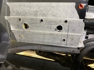
  3. Using masking tape mark up the offside transmission tunnel and floor as shown below.
  4. Use the footwell cover plate as a template and draw around marking outside line and all through holes.
  5. Follow diagram and cut out required area with reciprocating saw (drill larger hole inside cut out area to allow for saw blade entrance) and clean up edges using a file – the floor can be removed once marked up to ease cutting.
  6. Mask up around the cut out and drill holes and spray paint – slide some cardboard behind tunnel to prevent overspray onto gearbox.


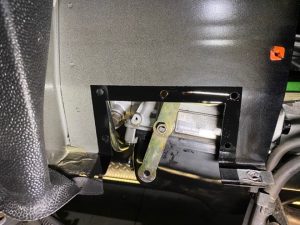
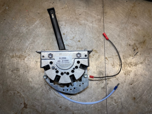
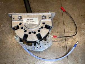
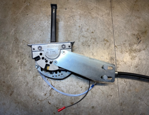
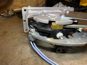
  1. Install potentiometer onto the potentiometer bracket in the shown orientation.
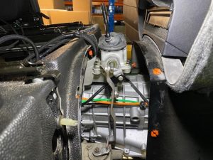
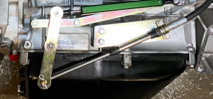
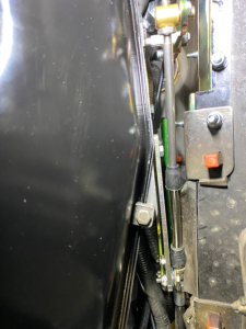
  2. Fit bracket to the gearbox along with lever and gear shifter lever to gearbox selector shaft using the supplied bolts and nut.
  3. Ensure position and orientation of levers on selector shaft is as shown below.


  1. Remove bonnet release lever and cable.
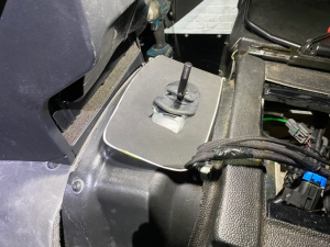
  2. Remove door open switch and plate.
  3. Pull back matting over all the pedals and towards the middle of the vehicle to allow access to clutch pedal bolts.

  1. Undo the 6 clutch pedal bolts.
  2. Unplug connector from clutch pedal. This plug can be cut off, isolated and tied away.
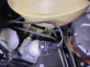
  3. Loosen radiator expansion tank bolt, lift expansion tank up and move towards the engine.
  4. Undo hydraulic clutch line from the pedal. You can cut this pipe behind the bends to help removal.
  5. On 2.4 models 3 electrical connectors will need to be removed from on top of the clutch pedal before removing.
  6. Remove the clutch pedal from engine bay, you may need to twist the pedal box on removal to allow pedal to pass through the hole.
  7. Install clutch pedal cover with supplied bolts and refit 2 of the clutch pedal bolts in the upper 2 holes with m8 nylocs to secure.
  8. Remove remainder of clutch line, this is easiest to do by pulling down on the clutch line from underneath.


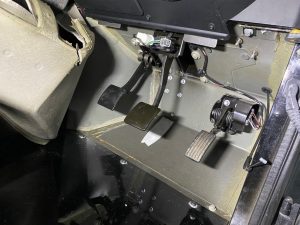
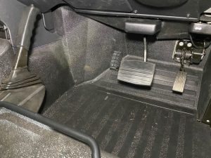
  1. Place auto brake pedal on the original, ensure mounting holes are centred and mark ready for drilling, you can also clamp the pedal on with mole grips whilst drilling.
  2. Drill holes out to 8mm (pilot first with 4mm drill) and secure with supplied countersunk bolts, use 3 M8 washers on each bolt to space the auto pedal away from the original to allow rubber cover to fit over the top.


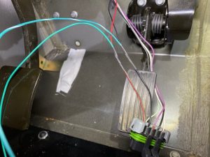
  1. Unplug connector from throttle pedal – The connector is marked alphabetically, the wires in holes ‘F’ and ‘G’ are required to splice into.
  2. Using supplied TPS Green & Green/White tails, splice the Green wire into ‘F’ (red/green trace) and splice Green/White trace into ‘G’ (black).
  3. Re-tape the wires of the connector using the cloth insulating tape.
  4. Using self-adhesive clips, route the TPS wires around the back of the footwell and towards the centre.


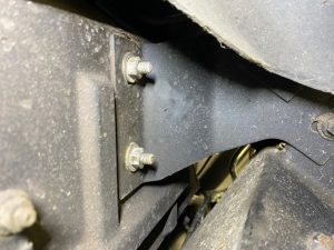
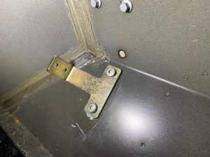
  1. For 2.2 models remove the tape in the footwell and remove the bolts, you will need to access the nuts for these bolts through the wheel arch.
  2. Mount the footrest bracket through these holes using the same bolts and nuts.


  1. For 2.4 models position footrest to left of footwell, copy the angle of the brake pedal and mark for drilling.
  2. Ensure it is safe to drill and there is nothing on the other side of the panel that will be damaged.
  3. Drill all 3 holes to 8mm, do not mount footrest until the matting has been refitted.
  4. Refit matting, bonnet catch lever, door switch and trim. You will need to cut a slit in the matting for the footrest to poke through.

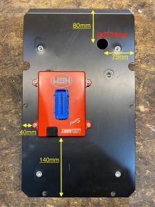
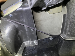
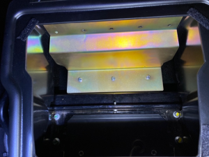
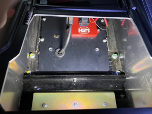
  1. Follow picture below to mount Compushift to the centre plate located under the cubby box.
  2. Use 4x M5 rivnuts to mount Compushift to the plate and drill out shifter cable clearance hole to 25mm.

  1. Use a sheet of Dynamat sound deadening on the underside of plate once drilled.
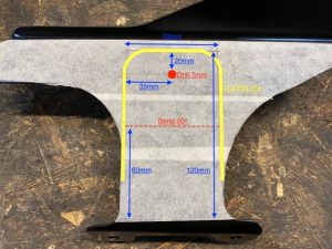
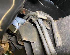
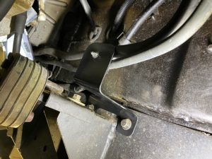
  2. Follow picture below and mark up fuel line bracket ready for modifying.

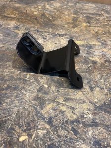
  1. Once the bracket is cut you need to bend along the dotted line, refit fuel line clamp and paint the cut edges black to avoid corrosion, see below.


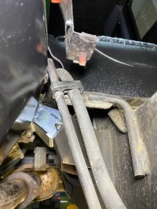
  1. Unclip front fuel line holder, bend the bracket 90 degrees, move the fuel lines to the other side and refit holder and secure fuel lines as shown.
  2. Refit modified fuel line bracket.


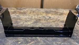
  1. Using an angle grinder and cutting disc remove the centre support just above the welds on the cross member.
  2. Grind down the welds flush and spray paint black.

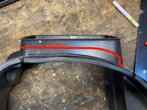
  1. See below pictures detailing modifications needed to transmission tunnel. Horizontal cut line is 25mm down from top of tunnel.
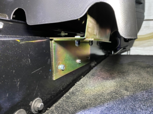
  2. Install curved bracket to right hand side of transmission tunnel using M6 bolt and Nyloc.


Main wiring loom preparation.

Wires to be removed/isolated –

Pin – Colour

80 – Brown

58 – Purple / White trace

69 – Blue / Red trace

49 – Blue / Orange trace

33 – Green / Red trace

70 – Blue

71 – Blue / Red trace

50 – Light Blue

51 – Blue / Black trace

44 – Black (to be re-used)

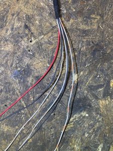
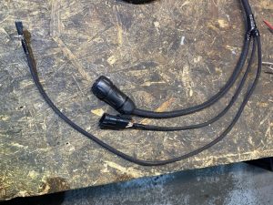
Once these wires have been removed then feed White / Brown trace (59) in along the same sheathing as the 12v power feed wire, mark the wire once fed through so it does not get confused with the other White / Brown trace.

Feed White / Orange trace (20) and White / Brown trace (19) down the same sheathing.

Feed White / Blue trace (60) down the same sheathing and pull out after approximately 45cm.

The Black wire (44) previously removed is to be fed in down the same sheathing but pull out just after the inline fuse and leave approximately 15cm and add a male red bullet connector.

Splice in 15cm of Red wire to the 12v Power feed (21) after the inline fuse and add a female red bullet connector.

Cut off the 3 pin connector from the Green TPS wires and discard, remove the rubber grommet also on these 3 wires and keep aside, this grommet will be used later.

Tape all flying wires together to aid fitting.

See below pictures for reference.


Wiring loom installation –

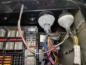
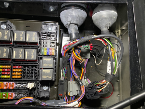
  1. Open fuse box cover located under drivers seat (RHD).
  2. Feed the flying wires in through the right-hand grommet.
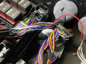
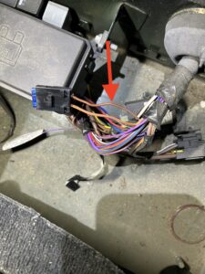
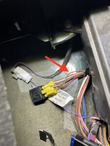
  3. For 2.2 models unplug the connector shown in the pictures and locate the Green wire and Black / Orange trace wire.
  4. Splice in the Red 12v power feed (21) to the green wire.
  5. On the relay loom, feed out the twin core wiring coming out of the relay that also has the Green / Brown trace wire through the right-hand grommet.
  6. The twin core coming out of the other relay is to have one wire connected to either side of the Black / Orange trace wire as shown in the pictures.
  7. Connect the Green / Brown trace wire from the relay loom to the White / Orange trace wire (20) on the main loom.
  8. Connect the White / Yellow trace from the relay loom to White / Brown wire (19) on the main loom.
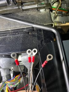
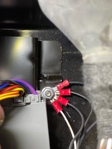
  9. Fit the 3 remaining Black wires and White / Brown wire with red 6mm ground loop connectors and ground all of them to one of the studs in the fuse box as shown.
  10. Use tape to secure and tidy up all the wiring.


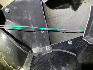
  1. Using cable ties, tie the main loom and the twin core to the vehicles wiring loom under the centre panel. Also secure any other wiring / plugs in the area and route under the body to come up through the transmission tunnel.

  1. Cut off the reverse switch plug off the vehicles loom and attach each end to the twin core as shown.


  1. Plug in the round connector into the gearbox, twist the end of the plug until it clicks to secure.
  2. Plug in the Potentiometer plug into the plug off the main loom.
  3. Run the Temperature sensor wiring down the right-hand side of the box and plug into the Temperature sensor.
  4. Ensure the temperature sensor wiring is secured close to the gearbox and well away from the prop shaft also make sure the potentiometer wiring is secured so that no stress is placed on the connector as the wires are very thin.
  5. Run the White / Blue trace wire (60) along the vehicle wiring loom up the back of the baulk head to the ECU.
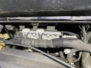
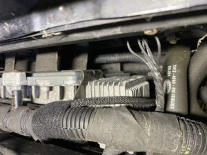
  6. For 2.2 models, unplug the top connector on the ECU and remove the tape and locate the Blue / Green trace wire. For 2.4 models you may need to remove the security screw holding the cage around the ECU connectors, this is easiest done but cutting a slit in the screw with an angle grinder and cutting disc then removing with and large flathead screwdriver, on 2.4 models it is the bottom connector you need to access.
  7. Splice in the White / Blue trace wire (60), re-tape and connect the plug to the ECU and secure the wire as shown below.


  1. The remaining Green (39) and Green / White trace (40) wires will be connected upon refitting of transmission tunnel.

Refitting interior –

  1. Refit passenger floor panel.
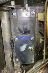
  2. Install supplied spire clips or use rivuts to the 5 holes for the footwell cover panel.
  3. Install footwell cover panel, you can either drill the 4 floor holes and use m6 nuts and bolts or use supplied spire clips and screws.


  1. Refit transmission tunnel. Pull all wiring through the top of tunnel, except Green and Green / White trace TPS wires, these to go under the transmission tunnel and routed down the side towards the drivers footwell.
  2. Fit Foam pad around Hi/Lo lever, push in tightly to secure and seal gaps.

  1. Connect the 2 TPS wires from the main loom to the 2 wires earlier spliced in the TPS connector. Green to Green, Green / White trace to Green / White trace.

  1. Insert handbrake cable back and handbrake light switch wire back through body, refit lever and connector, use some WD-40 to help push cable into lever.
  2. Refit floor matting / carpet.
  3. Refit Centre plate with Compushift.
  4. Plug in the Compushift and using tape tidy up any excess wiring.
  5. Turn vehicles ignition on and check Compushift powers up and displays red flashing light.

Fitting Centre Console –

  1. Remove inner tray and lower the front of the console in first, placing under dashboard and make sure Hi/Lo Stick comes through the cut-out in the console. Lower the back of the console down and ensure no wiring gets caught.
  2. For 90 models mark the 3 holes on the console support bracket, remove console and drill the 3 holes and install rivnuts, refit console and secure.
  3. For 110 / 130 models fit the console mounting bracket to the console support bracket using m6 fixings. Then drill through the body and bolt together using m6 fixings as shown below, use a helper to do up the fixings from underneath the vehicle.


  1. Fit supplied console Hi/Lo Gaiter.
  2. Fit supplied Hi/Lo knob.
  3. Test Hi/Lo and Diff lock function and make sure it does not foul the console.

Gear Selector Preparation –

  1. For Right-Hand Drive vehicles remove the gear knob assembly and surround trim.
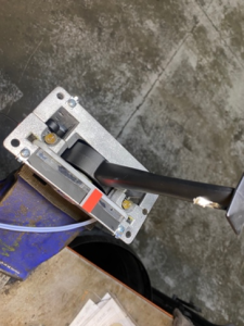
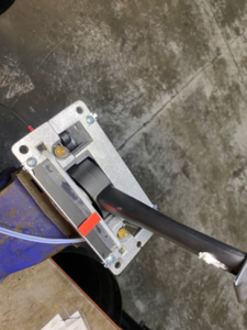
  2. Install position plate onto the shifter with the radius facing forwards, use a 15cm length of black wire with a 6mm red ground loop and install on the rear bolt, add a female red bullet connector on the other end, see photos below.
  3. Cut the two light blue wires for the bulbs to the same length as each other, strip and twist together and add a blue male bullet connector.
  4. Install the selector cable holding plate with the curved bracket and screws.
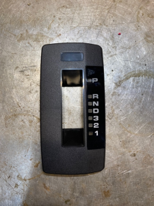
  5. Using a razor blade remove the orange indicator sticker and move sticker forward approximately 3mm and cut off the excess plastic showing.
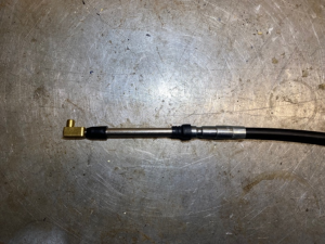
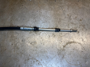
  6. Orientation of the shifter cable is important, the side that the inner cable slides all the way into the outer cable must attach to the gear shifter.
  7. Remove the nut from the gear shifter side of the cable and thread on the brass square nut approximately ¾ of the way on.
  8. Insert shifter cable into the 4th locating hole from the front on the gear shifter.
  9. Using the selector cable clamp assembly secure the cable to the mounting plate in positing 4.
  10. Slide the grommet previously removed from the Green TPS wiring on the main loom on to the selector cable.
  11. Add the Right-Hand Drive Gear Position Display to the surround trim and secure with the press clips.


     Gear selector side                                                            Gearbox side


Fitting Gear Shifter –

  1. Slide the Shifter assembly in through the cut out in the console and guide the cable through the 25mm hole drilled in the centre plate, ensure the cable goes between the fuel lines and wiring loom under the vehicle and aim the cable over the exhaust hanger towards the front of the vehicle.
  2. Push in the grommet to the centre plate.
  3. Drill the 4 mounting holes on the shifter to 5mm and secure with m5 cap heads and nylocs.
  4. Install the surround trim.
  5. Install gear knob with the button on the right, you will need to rotate the button 90 degrees.
  6. Test Gear Shifter has full range of motion and leave in Neutral ‘N’.
  7. Reach under the console and connect the blue wires from the Gear shifter bulbs to the Red wire coming from the main loom. Connect the black wire coming from the Gear shifter to the black wire coming from the main loom.
  8. Refit inner tray.


  1. Under the vehicle install the Gear Shifter Cable bracket to the cable using the clamp assembly as shown in pictures below.
  2. Feed the cable and bracket over the Gearbox mount and forwards towards to gearbox selector shaft.
  3. Bolt the bracket to the Gearbox using the m6 bolts supplied. This is fiddly! Only tighten by hand until 100% certain the bolts are threaded correctly then can be finished with a spanner.
  4. With the Gearbox also in Neutral (Check by moving the bottom lever on the selector shaft all the way forwards and coming back 2 positions) thread the brass barrel nut onto the selector cable until it aligns with the hole in the selector shaft lever with no resistance.
  5. Insert the barrel nut into the bottom selector shaft lever and secure with the supplied R Clip and tighten the lock nut onto the barrel nut.
  6. Check function of the Gear Shifter and ensure all position gates line up and the Gear Display indicator also lines up on the surround trim. Fine adjustments can be made with the position of the Gear Shifter cable barrel nut in the Selector shaft lever.


  1. Turn ignition on and check both display bulbs illuminate.
  2. Clean centre console with Dash Shine and microfibre once installation is complete.

Setting up Compushift –

  1. Turn vehicles ignition on.
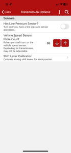
  2. Open Compushift Setup App on a smartphone.
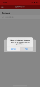
  3. Select Compushift and pair to device.
  4. From the Dashboard follow this sequence –

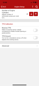
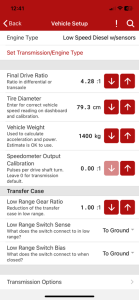
Back (top left) – Engine Set up – TPS Calibration – Start – Cycle throttle pedal from no throttle to full throttle back to no throttle (this needs to be done within the timeframe shown on the screen) – OK – Back – Vehicle Set up – Transmission options (bottom of page) – Shift lever calibration –

Put Gear selector in Park ‘P’ and press Set Park –

Put Gear selector in Reverse ‘R’ and press Set Reverse –

Put Gear selector in Neutral ‘N’ and press set N –

Put Gear selector in Drive ‘D’ and press Set D4 –

Put Gear selector in Third ‘3’ and press Set D3 –

Put Gear selector in Second ‘2’ and press Set D2 –

Put Gear selector in First ‘1’ and press Set D1 –

Press back until you get back to homepage and select Dashboard.

  1. Check ‘Throttle Position’ is at 0% with no throttle and 99% or 100% on full throttle.
  2. Check Gear Shifter positions match what is displayed under ‘Gear’ on the Compushift.
  3. Turn vehicles ignition off.


Filling Gearbox procedure –

  1. Have a helper sit in the vehicle with the ignition on, footbrake depressed, gearbox in Park and the handbrake on.
  2. Position extractor hose over exhaust tip and turn on the extractor in the welding bay.
  3. Position waste oil drainer underneath.
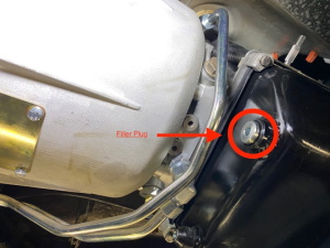
  4. Remove Gearbox filler plug.

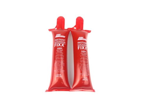
  1. Pour full bottle of Lube Guard into gearbox, use some hose pushed into the bottle to aid pouring.
  2. Using Automatic Transmission Fluid (ATF) Dexron 3, fill gearbox until it starts to spill back out of the fill hole.
  3. Have the helper start the engine.
  4. Continue filling with oil until level again spills out of fill hole.
  5. Cover fill hole and have helper cycle through each gear twice and leave back in Park.
  6. If no oil is now spilling out of fill hole then fill some more until it does.
  7. Refit Gearbox filling plug.
  8. Turn vehicles engine off.

Final checks –

  1. Refit Cross member.
  2. Check over work to ensure nothing has been missed.
  3. Check for any initial leaks after filling.

Test Drive and Leak check –

  1. Check on Compushift that there are no faults codes showing.
  2. Check Oil Temperature is reading properly.
  3. Check all gear changes are smooth and display on Compushift.
  4. Check the speed displayed on the Compushift matches speed displayed on speedo (Give or take 3 MPH)
  5. Check kick down operates as it should.
  6. Check torque converter locks at 56mph, Vehicle must be in 4th gear and under 80% throttle. Check engine revs drop roughly 750rpm when torque converter locks.
  7. Check Hi/Lo and Diff Lock functions properly following instructions on dash sticker.
  8. Raise Vehicle back up on the ramp and closely inspect for any leaks.

2 reviews for TDCi Defender Auto Kit

  1. John loughlin

    Love it

    I love my auto conversion. It makes my Defender so much more user friendly for every day use.

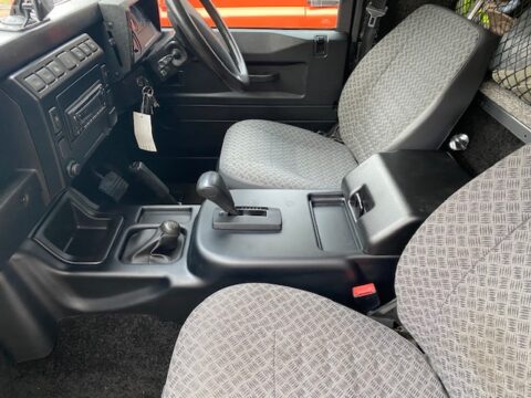
    I love the factory look inside the car – as if I came like it from LR.

    The car is great on a long run, cruises on the speed limiter without any problems.

    Have done several 1000+ mile trips into Europe without stopping and it copes perfectly.

  2. Bill Roberts

    Defender Delight

    I have always enjoyed driving my Defender but found the manual six tedious, now since having had my Defender converted to Auto it is an absolute delight to drive. Weather it be on short daily runs, longer motorway trips, challenging off road using in high and low box and towing, it’s a breeze.
    The professional approach towards producing this amazing auto conversion is also extended to the overall finish, a number of people looking at plate on the rear of my Defender and inside the car have said they didn’t know JLR did an auto Defender such is the quality of the work.
    Thanks to all involved in putting this smile on my face.
    Bill Roberts

Add a review

You may also like…

Go to Top